- Home
- Blog
- Equipment Info
- Cone Crusher Diagram: A Simple Explanation
- mmldigi
What is a Cone Crusher?
A cone crusher is a super important machine used in mining and construction. It’s designed to break down big rocks, ores, and other stuff into smaller pieces that are easier to handle. The machine gets its name from its cone-like shape, which has a fixed outer cone called the bowl liner and a moving inner cone known as the mantle. Cone crushers are usually used after primary jaw crushers in the second, third, and fourth stages of crushing. Learn how cone crushers excel in secondary crushing in What is Secondary Crushing? Basic Knowledge Should Know. They’re crucial for getting the material fed into them down to the size needed and making consistently sized aggregates for all sorts of uses. In mining, cone crushers are a must-have for processing raw ores and getting them ready for the next steps in mineral extraction. They’re versatile, efficient, and can handle a lot of material, which makes them essential for making sure crushing circuits and mineral processing operations are running at their best.
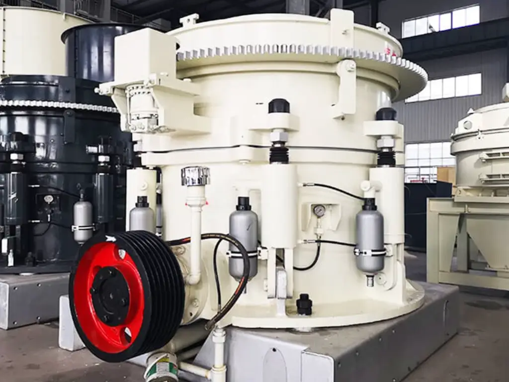
Applications of Cone Crushers in Mining and Construction
Cone crushers are used a lot in different industries, like:
Mining: They are employed in the crushing and grinding of raw ores, including limestone, copper, gold, and iron, into smaller fragments that can be processed further. Cone crushers are frequently employed during the second and third crushing phases.
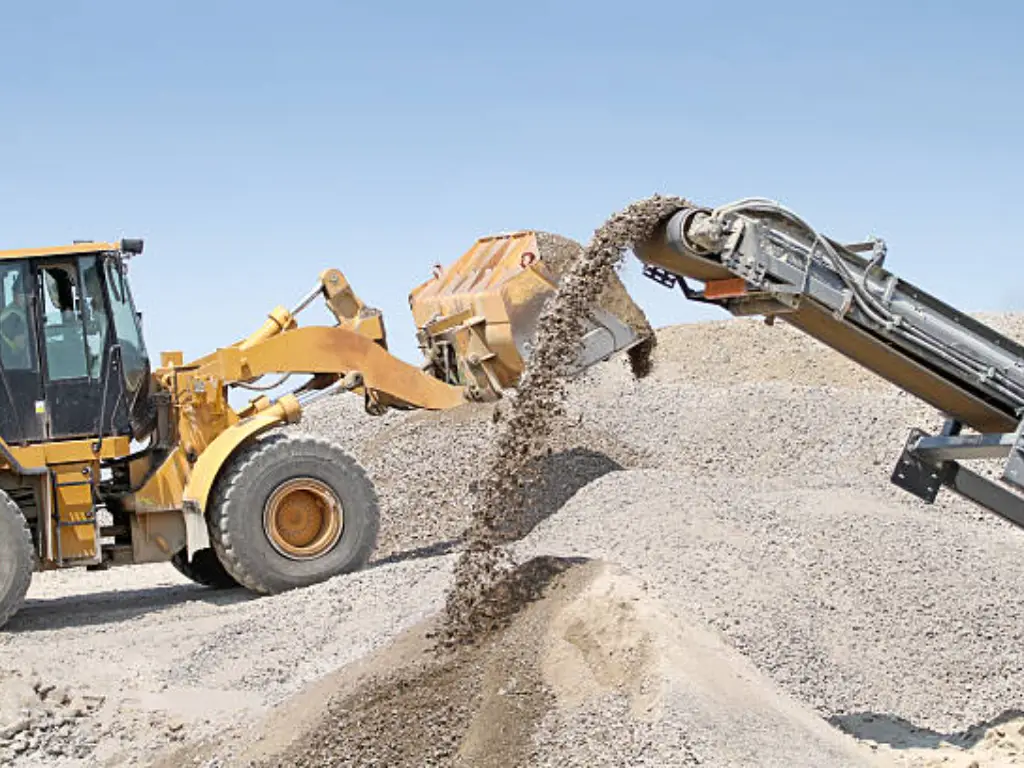
Construction: They are heavily involved in the production of high-quality aggregates used in the construction of concrete, roadways, and other infrastructure projects. They are employed in the crushing of hard rocks, such as quartzite, granite, and basalt, into various sized gravel, crushed stone, and sand particles.
Recycling: Waste materials such as asphalt, concrete rubble, and demolition debris are crushed and broken down into reusable aggregates, which contributes to more environmentally friendly building practices.
Cone crushers are really versatile and can handle different sizes and types of materials fed into them. They can be used on their own or as part of a bigger crushing and screening setup, depending on what the operation needs.
Main Components of a Cone Crusher
If you want to operate or take care of a cone crusher, it’s really important to know the main parts of the machine. By getting to know the cone crusher diagram, you’ll have a better idea of how the equipment works, be able to spot any problems, and do the maintenance that needs to be done. Let’s take a closer look at the key components of a cone crusher.
| Component | Location | Purpose | Function |
|---|---|---|---|
| Crushing Chamber | Central part of the crusher | Houses the crushing process | Consists of the bowl liner (fixed outer cone) and mantle (moving inner cone); determines the size reduction ratio and overall performance |
| Mantle | Inside the crushing chamber | Performs the crushing action | Made of wear-resistant materials; moves in a circular path to crush material against the concave |
| Concave (Bowl Liner) | Surrounds the mantle | Stationary outer cone | Made of durable materials; provides a surface for the mantle to crush material against |
| Liners | Fitted on mantle and concave | Protect main components from wear | Replaceable wearing parts designed to absorb impact and abrasion; need regular replacement to maintain optimal performance |
| Eccentric Assembly | Connected to the main shaft | Generates the gyratory motion of the mantle | Consists of an eccentric bushing, pinion shaft, and countershaft; rotates to cause the mantle's circular crushing motion |
| Adjustment Ring (Bowl Adjustment Ring) | Mounted on the bowl assembly | Controls the closed side setting (CSS) | Adjusts the CSS by raising or lowering the bowl assembly; determines the product size (finer or coarser) |
| Main Shaft | Central component of the crusher | Supports the mantle and transfers power | Connects the mantle to the eccentric assembly and supports the crushing forces |
| Spider Cap | Top of the crusher | Protects the spider bearing | Covers and seals the spider bearing to prevent contamination |
| Dust Seal | Between the spider cap and the top shell | Prevents dust and fines from entering the crusher | Seals the gap between the spider cap and top shell to maintain a clean crushing environment |
| Hydraulic/Spring-based Adjustment System | Connected to the adjustment ring | Enables CSS adjustment | Allows operators to adjust the CSS by applying hydraulic pressure or spring tension to the adjustment ring |
Anatomy of a Cone Crusher Diagram
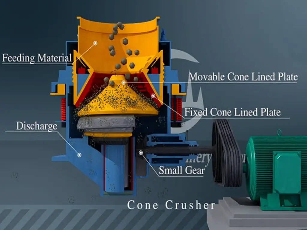
A cone crusher diagram shows the main parts of the machine. These include the crushing shell, eccentric shaft, adjustment ring, and bottom shell. The bottom shell is made from annealed cast steel. Safety devices protect the crusher.
The crushing shell has a fixed cone (bowl liner) and a moving cone (inner crushing cone or mantle). They form the crushing chamber. The eccentric shaft is made from manganese steel alloy. It’s powered by the crusher’s motor. It rotates in a special way, making the mantle move back and forth. This crushes the material against the bowl liner.
Material goes in the top feed opening. It gets crushed and moves down through the chamber. It comes out the bottom discharge opening. The adjustment ring changes the size of the discharge opening. It does this by changing the distance between the mantle and bowl liner. This determines the size of the final product.
The shape and structure of the crushing chamber are very important. They control how well the crushing works. They also control the shape of the product. As the mantle moves, the material gets squeezed, sheared, and bent. This breaks it into smaller pieces. The position of the cones and the chamber design affect crushing efficiency and product shape.
Safety devices prevent damage if the crusher gets overloaded. These include hydraulic accumulators or mechanical springs. They let the mantle move away from the bowl liner. This protects the parts. The step bearing, made from high grade forged steel and annealed for stress relief, holds up the main shaft. It’s designed to handle high stress. Special techniques like heat treatment make the step bearing and other parts last longer.
An electric motor and belt pulley system power the crusher. They connect to the eccentric shaft. The supporting structure may have springs or hydraulic cylinders. They keep the parts lined up and absorb crushing forces. Cone crushers can be fed in different directions. They often connect to other machines, like conveyor belts, for moving and processing materials.
Types of Cone Crushers
Cone crushers come in various types, each designed to cater to specific crushing applications and operational requirements.
| Feature | Hydraulic Cone Crushers | Spring Cone Crushers |
|---|---|---|
| Adjustment System | Hydraulic cylinder mounted on the main shaft allows for easy and precise adjustment of crushing settings | Relies on a spring-based adjustment system, where the main shaft is supported by a large compression spring |
| Overload Protection | Incorporates a hydraulic tramp release system that allows the mantle to move away from the concave during overloading, preventing damage to components | Limited overload protection; may experience damage if uncrushable objects enter the crushing chamber |
| Crushing Capacity | Higher capacity due to efficient crushing action and ability to handle a wider range of feed materials | Lower capacity compared to hydraulic cone crushers; suitable for consistent feed materials |
| Feed Size | Can handle larger feed sizes, typically up to 300-400 mm | Feed size is generally limited to 200-300 mm |
| Product Size | Can produce finer products due to precise adjustment capabilities; product size can range from 6-75 mm | Product size range is typically 10-100 mm; limited adjustment capabilities compared to hydraulic cone crushers |
| Efficiency | Higher efficiency and energy savings due to optimized crushing action and hydraulic system | Lower efficiency compared to hydraulic cone crushers; may require more energy to operate |
| Maintenance | More complex maintenance due to the presence of hydraulic systems; however, hydraulic components offer better protection against wear and damage | Simpler maintenance due to fewer complex components; however, may require more frequent maintenance due to wear of spring and other components |
| Adaptability | Can easily adapt to changing feed material characteristics and operational requirements; suitable for a wide range of applications | Less adaptable to variations in feed material; suitable for operations with consistent feed characteristics |
| Initial Cost | Higher initial cost due to advanced hydraulic systems and components | Lower initial cost compared to hydraulic cone crushers due to simpler design |
(Some material sizes and output capacity information depend on different models)
Example Analysis: Working Principle of Cone Crushers
In a gold mining operation, the raw ore is first taken from the mine to the crushing plant. The ore may have large boulders up to 1 meter across. It’s initially fed into a primary jaw crusher. This crusher breaks the big boulders down to about 150-200 mm.
The crushed ore is then moved by conveyor to the secondary crushing stage. A cone crusher is used here. The ore goes into the cone crusher’s feeding system, which usually has a hopper and a feed distributor. The feed distributor ensures an even and consistent flow of material into the crushing chamber. It easily handles the coarse materials.
As the ore enters the crushing chamber, it gets trapped between the fixed bowl liner and the moving mantle. The eccentric shaft, powered by the crusher’s motor, makes the mantle move in a circular, back-and-forth motion. This creates compression and release cycles inside the chamber.
During compression, the ore is severely crushed between the mantle and the bowl liners. The ore particles are pulverized and reduced in size as the mantle sinks. Upon release, the crushed particles descend further into the chamber as the mantle draws back.
The ore particles continue to descend down the crushing chamber, coming into contact with progressively smaller gaps between the bowl liner and mantle. The particles become progressively smaller as a result of the continuous crushing and compression.
The final size of the crushed product is determined by the cone crusher’s closed side setting (CSS). With the help of the crusher’s hydraulic or spring-based mechanism, the CSS—the smallest gap between the mantle and bowl liner at the bottom of the chamber—can be changed. Operators can achieve the desired product size by configuring the CSS appropriately.
The cone crusher in this gold mining system is configured to produce material with a 25–50 mm particle size, which is ideal for the tertiary crushing step. Conveyor belts transport the crushed ore to the tertiary crushing circuit when it falls out of the cone crusher’s bottom. Usually, this has another cone crusher or a high-pressure grinding roll (HPGR).
The ore particles are reduced to around 6–12 mm in the tertiary crushing stage, which is ideal for the ball mills’ subsequent stage. Further processing techniques, like flotation, are then used to the ground ore in order to concentrate the minerals that contain gold.
The performance of the cone crusher is monitored and adjusted during the whole crushing operation. To make sure the crusher is operating effectively and generating the required product size, critical parameters including feed rate, power consumption, and liner wear are routinely monitored.
Learn more about cone crusher mechanics in What is a Cone Crusher & How Does a Cone Crusher Work?
Cone Crusher Performance and Optimization
Closed Side Setting (CSS)
To optimize cone crusher performance, operators should monitor and adjust the following settings:
Crusher speed:
Feed rate:
Liner selection:
Closed side setting (CSS):
1. Depending on the model of the crusher and its intended application, the CSS typically ranges from 6 to 75 mm. For instance, a 12 mm CSS would be suitable for producing fine aggregates, while a 50 mm CSS might be effective for crushing medium-hard rocks.
2. A little 2-3 mm alteration in CSS can have a significant impact on product size distribution and capacity.
Crusher speed:
1. Generally speaking, cone crusher speeds range from 600 to 1,000 RPM, depending on the size and brand.
2. For example, while crushing hard rock, a 7-foot cone crusher may perform best at 750 RPM.
3. A 10-15% increase in capacity can be achieved by increasing the speed by 50 RPM. However, the product may contain more fine particles as a result.
3. A 10-15% increase in capacity can be achieved by increasing the speed by 50 RPM. However, the product may contain more fine particles as a result.
Feed rate:
1. Feed rates might differ significantly depending on the size of the crusher, the material being crushed, and the desired output.
2. For instance, the feed rate of a 5.5-foot cone crusher used to process granite could be 200–300 tons per hour.
3. A 15% overload on the crusher might result in a 5–10% reduction in capacity and accelerate the wear and tear of the liners and other components.
Liner selection:
1. Standard, heavy-duty, and ultra heavy-duty liners are available, depending on the degree of abrasiveness of the material.
2. For instance, crushing extremely abrasive sandstone would require extra heavy-duty liners with a 500,000-ton lifespan, whereas less abrasive limestone might just require ordinary liners with a 1,000,000-ton lifespan.
3. Choosing the appropriate liner profile (low-profile for finer output, high-profile for coarser output) might help maximize performance for certain product requirements.
Maintenance and Troubleshooting Tips
If you want cone crusher to keep running smoothly and last a long time, regular maintenance and quick troubleshooting are super important. Here are some key tips to keep in mind:
– Before the concave liners and mantle get too worn down, be sure to check them and swap them out. This stops other parts from getting messed up and keeps the crushing efficiency nice and high.
– Keep an eye on the lubrication system to make sure the crusher has enough lubricating oil. Using the right oil cuts down on friction, stops the crusher from overheating, and helps the parts last longer.
– When the crusher is running, keep your ears open for any weird noises or vibrations. These could be signs of problems like loose parts, worn-out bearings, or stuff that shouldn’t be in the crushing chamber.
– Don’t let fine particles and gunk build up inside the crusher; keep it nice and clean instead. If too much material piles up, it can make the crusher less efficient and cause the liners to wear down unevenly.
– To keep the crusher running like a well-oiled machine and to handle any changes in the material being fed into it, regularly check and adjust the crusher’s settings, like CSS and speed.
Conclusion
To wrap it up, a cone crusher diagram is a seriously useful way to see and understand the main parts and how these awesome crushing machines work. By really getting to know the nitty-gritty of cone crusher diagrams and using the best tips and tricks for running and taking care of them, folks in the mining and construction business can unlock the full potential of these powerful machines. This can lead to better production, bigger profits, and overall crushing performance that’s totally unbeatable.

