- Home
- Blog
- Equipment Info
- An Easy Guide to Jaw Crusher Diagram
- mmldigi
A jaw crusher is an indispensable tool in the mining and construction industries, known for its power to fragment hard materials such as rock and minerals. Comprising type of jaw crusher—the robust Single-toggle and the efficient Double-toggle—these hefty machines operate on the principle of compressing materials between a stationary “fixed jaw” and a moving “swing jaw,” attached to an eccentric shaft. This powerful action makes the jaw crusher the go-to equipment, laying down the foundational work in various industrial applications.
Basic Components and Functions of Jaw Crushers
| Component | Function | Key Notes |
|---|---|---|
| Fixed Jaw Plate | Serves as the stationary breaking surface. | Made of high manganese steel for durability and wear resistance. |
| Movable Jaw Plate | Moves back and forth against the fixed plate, crushing the material in between. | Attached to the swing jaw; oscillates via the eccentric shaft. |
| Eccentric Shaft | Converts the rotation of the drive motor to the reciprocating motion of the swing jaw. | Made from high-strength steel; positioned to create an angle for effective crushing action. |
| Toggle Plate | Provides support to the bottom of the movable jaw. Acts as a safety device. | Breaks under extreme load, protecting the crusher from damage. |
| Conveyor Belts | Transport the crushed material to the next stage or storage area. | Must be durable and capable of handling the output rate of the crusher. |
| Feed Opening | The initial opening where material is introduced into the crusher. | Size dictates the maximum feed size and influences the crusher's capacity and production rate. |
| Discharge Opening | The bottom opening where crushed material exits the crusher. | Adjustable; dictates the maximum size of the output material. |
| Bearings | Support the eccentric shaft and the swing jaw, enabling their movement.Support the eccentric shaft and the swing jaw, enabling their movement. | High-quality bearings reduce wear and tear, ensuring longer operation life. |
| Toggle Block | Allows for fine adjustments to the jaw setting. | Enhances the crusher's performance and operational efficiency. |
| Hydraulic Systems | Facilitate automatic adjustments and safety features like clearing jams. | Modern crushers may include hydraulic toggle adjustment for easy CSS changes. |
| Reduction Ratio | The ratio of the feed size to the product size. | A high reduction ratio indicates a powerful crushing capacity. |
Learn how each part functions in our Simple Guide: How Does a Jaw Crusher Work?.
Anatomy of a Jaw Crusher
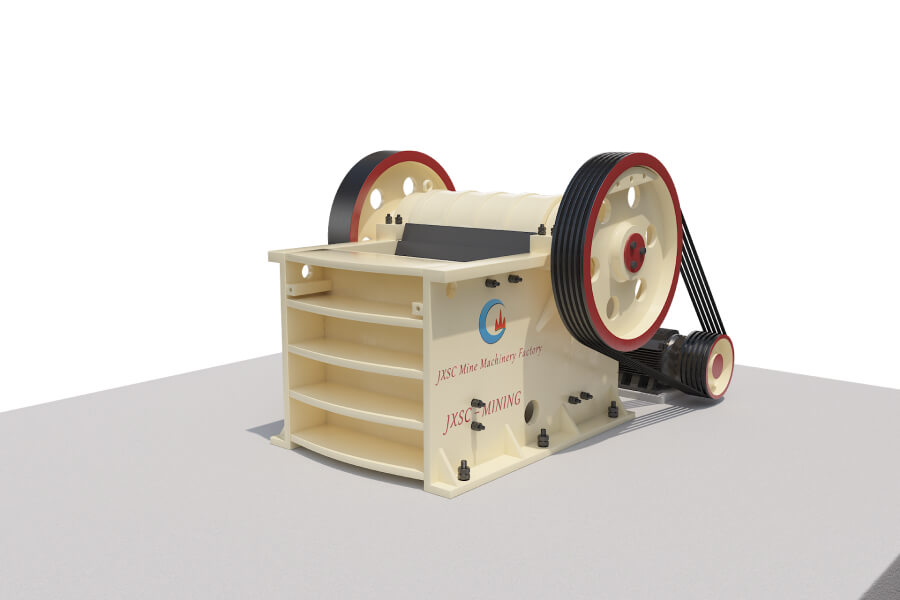
Every jaw crusher diagram is a window to the soul of this rugged machine, providing vital insights to the components that make up its robust design. At the heart lies two pivotal plates: the fixed jaw and the movable jaw. The fixed jaw, as the name suggests, remains stationary and serves as the backbone for the crushing process. Mounted securely to a steel frame, often made of cast steel for optimal durability, it supports the entire crushing operation. On the other side, the movable jaw, powered by an eccentric shaft, oscillates—delivering the force necessary to crush the material introduced into the machine.
The movable jaw is anchored in place by the toggle plate, a crucial piece that not only supports the jaw but also offers the safety of breaking under extreme loads, protecting the machine from potential damage. The job is demanding and the toggle plate is up to the task, made from high-strength steel, it withstands the daily grind of the crushing process.
Dynamic Crushing Actionv
When we talk about the crushing action, we’re referring to the process that transforms large, boulders into smaller, manageable pieces fit for construction or further processing. It’s this dynamic crushing angle and action that sets the jaw crusher apart as a primary crusher. The manganese steel jaw plates, one fixed and the other oscillating in a rhythmic pattern, exert compressive forces that shatter rock and mineral with remarkable efficiency at the receiving opening.
Manganese steel is revered in mining and construction for its unparalleled wear resistance and durability, allowing jaw crushers to handle feed with varying degrees of hardness and abrasiveness. Whether processing soft limestone or the more resistant iron ore, the wear on these manganese steel plates is gradual and uniform, ensuring a consistent feed and output size.
The dimensions of the crusher’s feed opening play a crucial role in determining the machine’s capacity. Interestingly, the size of the opening not only dictates the maximum size of the feed material it can accept but also influences the crusher’s overall production rate. A larger feed opening can accommodate bigger chunks of material, enhancing the crusher’s ability to chew through massive volumes of raw material.
Conveying Crushed Material
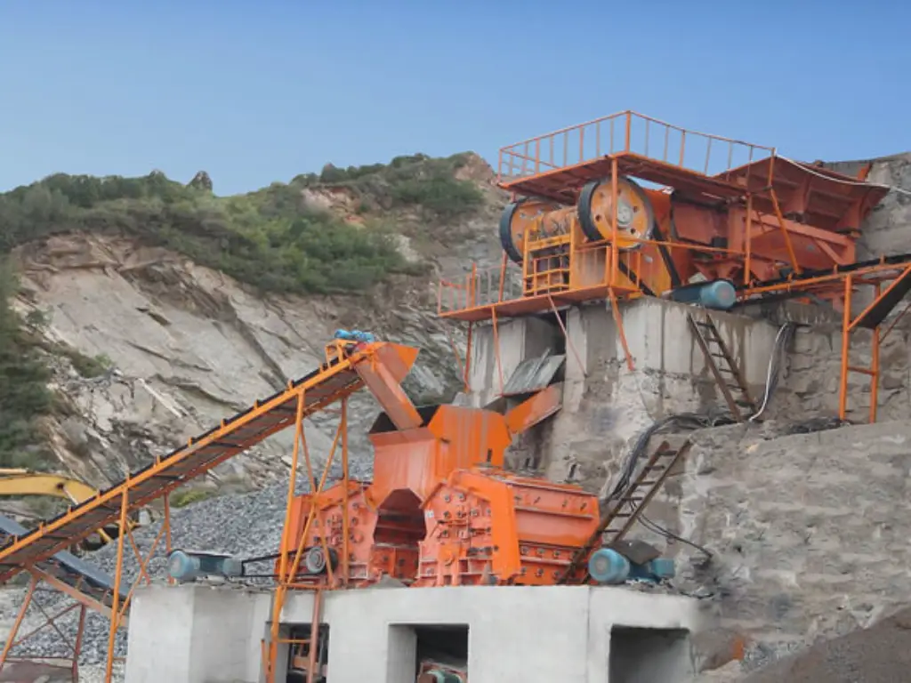
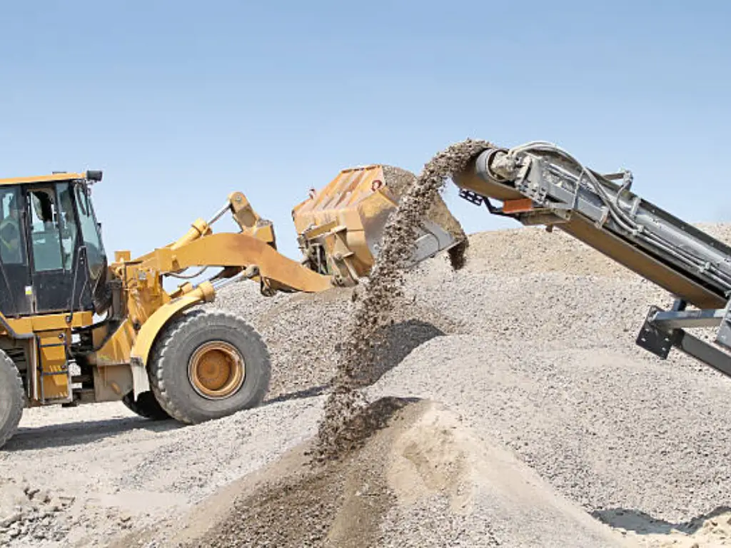
After we’ve crushed the material, conveyor belts step up to the plate—though they’re often missed when we’re eyeballing a jaw crusher diagram. These trusty conveyor belts lug the broken-down goods to where they need to go next, be it a pile ready for use, another crusher to break them down further, or straight to a ball mill for the next steps. Making sure the conveyor belts can handle the crusher’s output keeps everything ticking along smoothly, so that precious material keeps moving without a hitch.
In a busy mining setup, you really can’t do without these high-capacity conveyor belts. Together with a jaw crusher—a real powerhouse in its own right—you get a dynamic duo that forms the heart of moving materials around in the industry, capable of shifting massive amounts of stuff throughout a working day. It’s this tag team that brings the whole crushing circuit to life.
Dissecting the Internal Structure and Motion Process of Jaw Crushers
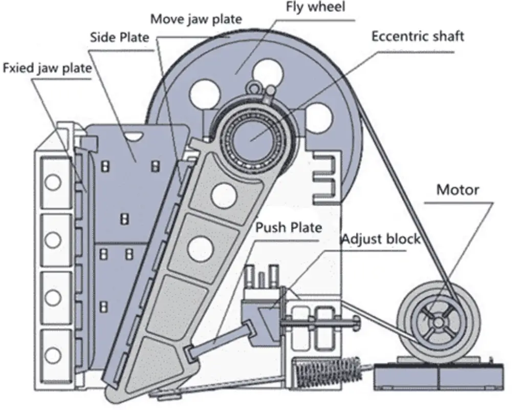
Let’s delve into the jaw crusher diagram—a revealing illustration showcasing the trajectory of the movable jaw plate. In action, this plate swings on the eccentric shaft, applying a forceful compression to the material against the fixed jaw. The movement is a simple yet effective-a vertical motion for heavy-duty crushing tasks, executing a powerful crushing action based on the working principle of the machine.
The process starts when feed material enters the feed opening, often measured in terms of diameter—from a modest 10 centimeters for small operations to a significant 2 meters for larger industrial machines. From there, the material encounters the crushing chamber, where the magic happens. As the swing jaw moves towards the fixed jaw, the space in the crushing chamber narrows, exerting intense pressure on the material between the jaw plates. This action crushes the material, which then moves further down the chamber.
As for the discharge process, it’s fascinating how meticulously the size of the crushed material is controlled. A crushed piece moves to the bottom of the jaw, and, if it’s small enough, it passes through the discharge point, which could have an adjustable opening to dictate the maximum size of the output. Some models boast a discharge opening that can be finely tuned, ranging from 3 to 20 centimeters, adapting to diverse needs from fine sand-like material to larger pebbles.
Now, onto the cast steel construction of the frame, a critical aspect highlighted in the jaw crusher diagram. This steel frame imparts formidable strength while providing a durable housing for the crusher parts, contributing to the overall longevity of the machine. This is particularly relevant in the mining operation where the equipment undergoes considerable stress, grappling with rocks of various compressive strengths—some can withstand up to 600 MPa, highlighting the need for a robust machine structure.
Diagrammatic Representation of Jaw Crusher Movements
What sets the single toggle apart in the diagram of a jaw crusher is its rocking motion. When analyzing the motion within the crushing chamber, we observe that the swing jaw’s bottom moves in a small arc, conducive to powerful crushing at the bottom. This is particularly potent when considering the handling of abrasive materials which demand a high reduction ratio.
Comparing this dynamic to the Double-toggle, or Blake crusher, its diagram depicts a more complex motion but provides a consistent crushing cycle. In such a machine, compressive forces are applied more uniformly across the jaw plates, distributing wear evenly and enhancing durability.
The toggle plate plays a pivotal role in this intricate dance between the jaws. Acting as a safety mechanism within the steel frame, this plate will break under excessive stress, preventing potential damage to the machine—reflecting intelligent crusher design. To add to this, manganese steel is often the choice material for jaw plates, boasting high-impact strength and an ability to wear down evenly, instead of developing sharp edges that could cause inconsistent crushing.
This back and forth, the reciprocity of the moving parts, stresses the importance of bearing choice in the swing jaw’s operation. High-quality bearings, embedded within the steel construction, endure the machine’s heavy vibrations and loads. This is essential in the mining context where downtime can be incredibly costly. A well-designed toggle block, placed at the rear end of the frame, augments this sturdy assembly by enabling fine adjustments to the jaw setting for optimal performance.
The machinery’s high-impact movement typically relates to a high production rate in a primary crusher. For instance, a standard jaw crusher diagram might show a feed rate of 500 tons per hour, translating to processing massive volumes like 1200 cubic meters of limestone or iron ore in a single day—a testament to the machine’s indispensable role in large-scale mining operations.
Adjusting and Measuring Jaw Crushers
The jaw crusher diagram is instrumental when it comes to adjustments for altering the granularity of the output. One critical metric is the Closed Side Setting (CSS)—the smallest gap between the jaws during the crushing cycle. Adjusting CSS is a straightforward affair and can make a significant difference in your output’s size and quality. If the CSS is set at 5 centimeters, for instance, that will be the maximum size of material that can exit the crusher, anything larger gets recycled through until it can pass.
Utilizing leading techniques for measuring this gap is vital to ensure consistent product size. A common approach involves lowering a lead weight into the crushing chamber, retrieving it, and measuring the thickness—this provides a gauge of the space when the jaws are closest together. Operators should ensure that the jaw gap is set correctly, as even a couple of millimeters can impact the reduction ratio and overall crusher efficiency.
Modifying the size of the discharge opening is also imperative for controlling the feed rate and performance. The equipped toggle block allows fine-tuning to cater to different sizes of the material, which is often drawn into the crusher via a robust steel conveyor belt. When the movable jaw is at the peak of its motion, the opening is at its widest, and the material freely drops through the hopper—pertinent information captured in every jaw crusher diagram.
The jaw plates, made of abrasion-resistant manganese steel, are designed for easy adjustment—yet another feature typically highlighted in crusher diagrams. This flexibility in the jaw crusher’s design allows users to replace worn plates without extensive downtime, ensuring steady operation and longevity of parts.
Understanding Performance Parameters of Jaw Crushers
The feed size, which often varies from small, fine pebbles to larger rocks up to 80 centimeters in diameter, greatly determines the crusher’s throughput. Matching the feed size to the jaw opening ensures maximum efficiency – for mining operations. This attribute is integral.
The throw—the horizontal movement of the swing jaw—also dictates performance. A longer throw often results in a higher throughput, albeit at the potential cost of increased wear and tear on the toggle plate and the entire machine. Meanwhile, a jaw plate design geared towards specific mining or cement plant needs can drive high productivity. For instance, reversible jaw plates can extend the useful life of the machinery.
In a crusher’s design, attention to the reduction ratio is critical. This ratio reflects the degree to which the material is reduced in size from the feed to the product. A high reduction ratio indicates a powerful crushing capacity, such as reducing 150-centimeter-wide iron ore to a 30-centimeter-wide material. The higher the reduction ratio, generally, the fewer stages are needed in the crushing circuit, improving cost-efficiency.
Design Optimization of Jaw Crushers
Keeping up with the push for efficiency and the need for low-hassle upkeep, jaw crushers have gotten some smart upgrades. Now, we’re seeing new models packed with features like hydraulic tech and handy auto-adjust settings. You can see these neat tricks in jaw crusher diagrams, which show us how these additions make the whole crushing game a lot smoother, cutting down on those unwanted stoppages.
Take hydraulic systems, for instance. They’re a game-changer when you hit a snag because they clear jams super quick and keep things safe. Also, with auto-adjustments, the crusher keeps the CSS and the size of the stuff coming out just right, all the time. Think about how sweet it is to tweak the CSS on the fly with hydraulic toggle adjustment – just a button press and no more wrestling with manual settings. For more insights on various jaw crusher models, check out Mineral Processing Solutions: Exploring Types of Jaw Crusher.
It’s not just about the fancy tech, either. Tweaks in the design help keep your wallet happy by slashing maintenance time and cost. Ever heard of bearing houses that you can pop out and replace? They make fixing parts a breeze, which is just one way new designs are upping the lifespan of these machines, especially when they have to tough it out in mining sites. Plus, nowadays, it’s pretty standard to have crusher parts, like the liners, made of super tough manganese steel, so they last longer and don’t corrode as quickly.
Conclusion
To wrap things up, let’s talk about how essential the jaw crusher diagram is for folks working in the biz. This nifty diagram lays it all out, helping us get the scoop on the meat-and-potatoes of a serious chunk of gear that’s key in both the mining and construction worlds. From crucial bits like the eccentric shaft to the hardworking toggle plate, every part has its moment to shine in the crushing game, and the diagram makes sure their teamwork shines through.
Reading a jaw crusher diagram like a pro is something you just can’t skimp on if you want to boost how well the machine works and cut down on the time you spend fixing stuff. It powers up those who run the show to make smart calls – like getting that CSS just right or figuring out the reduction ratios to get the crusher working just how they need it to, based on what they’re breaking down and the goals they’ve got their eyes on. In the grand scheme of things, these diagrams aren’t just fancy drawings; they’re like the north star for folks aiming for top-notch results.

